- Brazil: contato@construbrick.com.br
- USA: contact@construbrick.com.br
- Voice: +1 917 438 8700
TÍTULO
INFORMAÇÕES DO PROJETO
National Museum Of Qatar - Connections between Disks with Different Geometries
The National Museum of Qatar is the flagship in
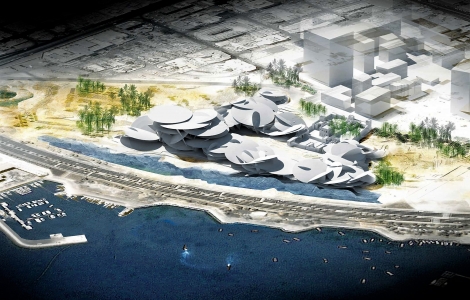
a series of national cultural and educational projects. Inspired by desert
rose, the museum is a four story, 300 meters by 200 meters sculpture of
intersecting disc shapes up to 80 meters in diameter. The structural solution
settled on radially and orthogonally-framed steel trusses, supporting
fibre-reinforced concrete cladding panels to create the required aesthetic and
performance of the building envelope.
Structural Modeling
The key challenges for the design resulted from
the highly complex geometry of the disc interaction.
The spaces in the building
are created by the interstices between the discs; any alteration to the
architecture involves moving discs and thereby moving the structure within the
discs.
The structural team developed a parametric
Generative Components script-based tool to automatically create wire-frame
geometry in the correct position within the architectural Rhino envelope. The
basic wire-frames were further populated with property and loading data using
spreadsheet-based automation. Custom-designed spreadsheet macros were further
used to combine separate disc models into larger combined models for structural
analysis.
Element strength checking was automated as far as possible, to make
practicable the design of the 250,000 steel elements. The analysis models were
used as the basis of the production Tekla model, directly translating geometry,
section data and also key annotation such as disc-to-disc interface nodes.
The Tekla model was issued to the contractor at
tender stage for accurate pricing. The model has been kept up to date and
reissued as the design has been completed, and contains the live drawing files
needed to communicate information in 2D.
On site, the contractor has adopted
and developed this model to a fabrication level of detail, and made use of
Tekla phases and classes to keep track of issue status of recent updates. Also
at tender, the Tekla model was used to interrogate concrete volumes in order to
produce accurate steel reinforcements.
Superstructure Steelwork Connections
The scheme for the building involves many
intersecting steel framed discs and therefore results in numerous connections
between discs with different geometries. An effective normalized solution was
established through a connecting CHS where a significant number of connections
are based.
It tolerates a large range of incoming member arrangements. To
communicate this to the contractor, connections were designed, detailed and
illustrated on drawings with 3D perspectives and 2D sections. The nature of the
each connection was such that the geometry and therefore design could not
properly be understood without interrogation of the intersecting members in 3D,
for which Tekla was invaluable.
Key Processes
1600 individually designed piles with bespoke
trim and toe levels were carried out in Tekla using a macro script to read the
required data from design spreadsheets.
Drawing and labeling of interface connection
tags in 3D space was carried out using a combination of the GSA to Tekla plugin
to create spherical objects at the required ânodeâ locations, and spreadsheet
lookups were used to compare and update those object properties from the
labeled connection nodes in the analysis model.
Clash checking was carried out in Tekla
BIMsight with the same .ifc exports as for MEP coordination. Verification of
the drawn structure was made possible by visual checking of the Tekla model
using the Tekla viewer, model reviewer and web viewers, and spreadsheet scripts
to automatically compare geometry and sizing from Tekla and GSA text data
outputs.
Effective communication with off-site/remote
technicians around the world was possible using the Tekla comment tool plug-in.
This captured comments and marked up screenshots, but could also be stored in a
live âcloudâ type server account for sharing with the design team, without
downloading and updating new files.
Challenges Solved using Tekla
Tekla BIMsight was instrumental in identifying
and resolving clashes within the production model, focusing engineering input
in the right places.
The complex 3D structure was broken down into
2D âcomponent drawingsâ for each disc, in order to communicate the design
clearly and succinctly to complement the clientâs contract hierarchy.
The Tekla model was a key input into the teamâs
Digital Projects BIM model to effect cross-discipline coordination.
Connection design was carried out in
collaboration with fabricators, identifying and modeling ârealâ geometry
examples to communicate connection design intent in 3D.
Teklaâs system of phase identification and
coloring was essential in identifying and tracking change for the contractor.
Fotos


